PWM and EFIE Installation Instructions Petrol – Updated March 9 2025
Special Instructions for Trucking installation—- MUST READ
This is for Hydrogen system Installation on Trucks with Compressors. (and all trucks / cars with air brakes).
Air for the Compressor is normally drawn off straight after the Primary/ Secondary Air filter assembly.
THIS MUST BE CAPPED OFF.
An alternative air Intake line with a filter MUST Be Installed to provide the Air to the compressor. Not doing this has the Potential of accumulators being pressurized with a mixture of Hydrogen Gas
Installation should be completed by a qualified Auto electrician , Un-qualified installation will void warranty. It’s not that the instructions are hard to follow, but rather unqualified installers are often found to take shortcuts and fail to install the system correctly.
Hydrogen Installation Instructions Petrol / Gasoline engines. Installation Instructions HFS-system trucking. Below is the link to read how to install the Hydrogen generator systems on your petrol fueled vehicle or generator. These instructions are a PDF file document. It is advised to print out the document and carefully read before attempting the installation.
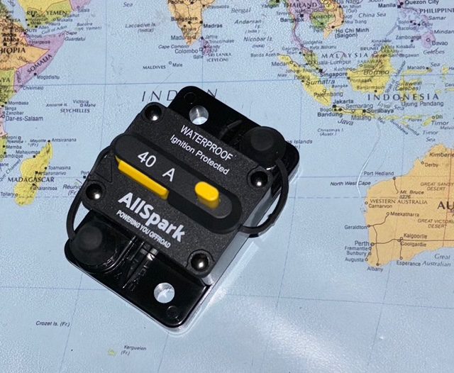
Bubblers / flashback arrestors must be always used with with Hydrogen systems from Hydrogenfuelsystems pty ltd to prevent flashback or backfire . 30 amp manual Reset Circuit breakersand 60 amp Solenoid relay (Power supply configuration 2 see below) must always be installed on Trucking systems and 30 amp Circuit breakers(PROVIDED) and Continuous Duty 60 amp Relay(Power supply configuration 2 see below) used on all other vehicles /engines.
For vehicles with Power Supply Configuration 1 (see below) The vehicle should be fitted with a 40 amp circuit breaker and relay
For more information on the installation of these patented Hydrogen Generator kits on your petrol fueled truck, car or generator read on . Then send me a message a message to glknox11@live.com, to clarify any aspects of the Installation Instructions.
Petrol Fueled engines can further improve the fuel savings by installing a tune-able / adjustable electronic fuel enhancer module that forces the engine to use a leaner and more powerful fuel map in your vehicle ECU.
Systems must be fitted by a qualified automotive electrician. This is not a DIY assembly
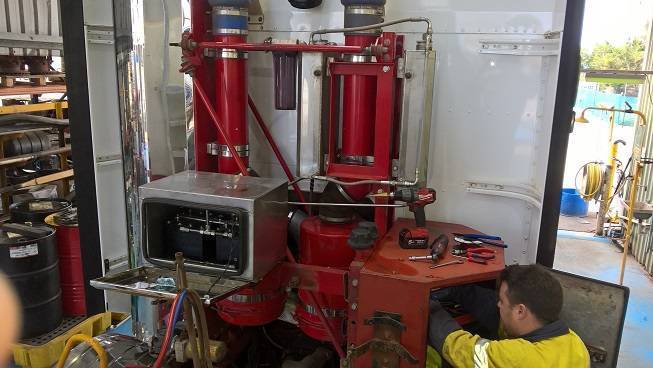
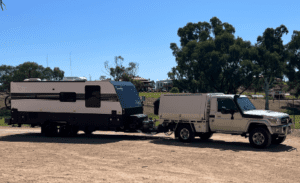
4.2 liter Toyota using Gen 15 system to tow caravan 2023 mounted in white box below vehicle tray in front of rear wheel (driver’s side)
Warning
Do not use a concentration of caustic higher than the recommended value ( as shown below) (11 grams /3 liter ) as this may lead to excessive heat generation electrolyte loss.
Having a low concentration of caustic is ideal as more energy is used into the oxidation / reduction of water into hydrogen and oxygen, rather on the “redox”. of the caustic….
Greater efficiency = more gas with less electrical load
Congratulations!
You have made a good decision in purchasing a “ Hydrogen Generator” System. Properly installing and using this device will make a significant contribution to both your own well-being and the well-being of the world you live in.
Getting started: Note!
Getting started: Note! If you are installing the “Hydrogen generator system” on a turbo charged engine you must route the Hydrogen transmission hose to a location UPSTREAM of the turbo, that is, on the LOW PRESSURE side of the turbo, in the air-intake cowling, or into the mouth of the air intake cowling, if you can access it.
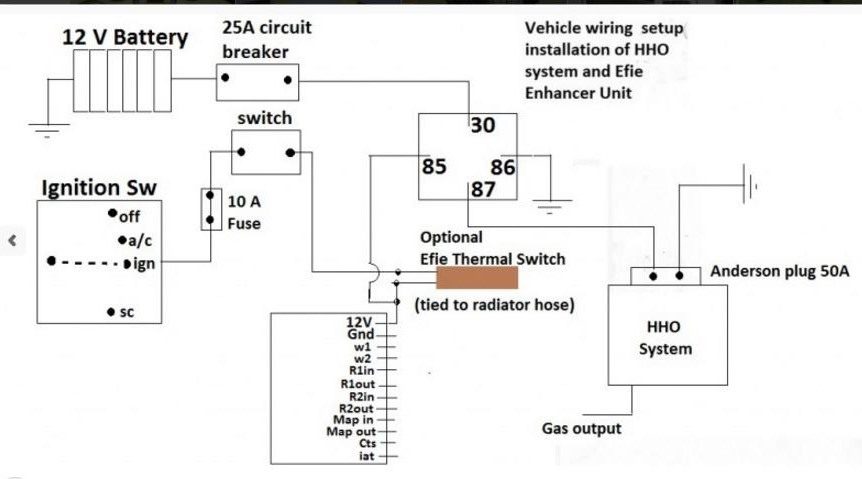
Power supply configuration – Better choice ( with 3 kW PWM supply- fitted) – 2024 edition
Materials required
30 amp Circuit Breaker, 60 amp Solenoid relay unit, Bubbler Unit, 4 m length 10 mm pneumatic tubing, 5 m double insulated 8 mm twin core cable, 12 volt master switch, potassium hydroxide, Distilled water, 3kW Pulse width modulator Unit fitted.
This configuration is used with the Pulse width Modulator power supply, running at 12 volts.
Initial setup when system is new
Fill the system so that the 3 litre recycling tank is holding 2.5 litres of distilled water.
Measure 15 grams of potassium hydroxide = one level teaspoon full – and mix this with 100 mls of distilled water.
Turn on the PWM power supply to fully on position .
Switch on the system with the pump running and add the small amounts of the 100 ml mixture to the recycling tank. Watch the current rise over the next few minutes stop adding any more mixture once the current reaches 15 amp.
Ensure the solution in the 3 litre recycling tank is 25 mm below the top of the tank (AS MARKED ON TANK)`. Add distilled water if needed to bring tank to correct level
Check the bubbler tank and ensure it is ¾ full of distilled water
Check the recycling pump is operating.
Measure and record in the chart the current flowing in the system and ambient temperature
The Initial Current flow should be operating at 15 amp. If Current is above 15 amp, syphon 200 mls of electrolyte from tank and replace with distilled water.
As the system is run in on your vehicle the starting current will rise to between 20 and 25 amp.
This starting current should now be adjusted using the control on the PWM power supply dial.
DO not wind back the current by more than 2 amp from the fully on position as this will lead to excessive heating of the PWM unit as it passes excess current through the heat sink
Drive the vehicle. As solution is used the concentration of the solution increases and current will rise. The system will use 1 litre of water every 10 hours
As the system is run in the current will rise towards 28 amp – correct operating current.
If the circuit breaker switches off you need to remove 200 ml of electrolyte and replace it with 200 ml of distilled water. This is a tuning procedure that may need repeating until you achieve a stable system.
Refill the solution with distilled water every 15 hours of operation or when the fitted circuit breaker switches off .
Once the distilled water is replaced , run the system for 3 minutes to allow the solution mixture to return to original concentration.
24 volt vehicles Must reduce the voltage to the power system to 12 volt output using an electronic voltage inverter.
One litre of water should last 8-10 hour s of continuous operation. One litre will last 9 to 10 hours of stop/start city driving.
Add water to recycling container to bring it to the full mark –8cm from top of tank.
After 3 months of operation, the liquid should be flushed out and drained. New/Fresh solution should be used.
For trucks and other engines using a 24 volt MUST install a device to lower the supply voltage to the system to 12 volt. For these large trucks one litre of water should last between 5 to 6 hours of continuous operation.
The “Hydrogen Generator system” is NOT a toy. This Hydrogen generator dry cell System can produce LARGE amounts of explosive Hydrogen gas. Do NOT use or experiment with the Hydrogen generator in unventilated or poorly ventilated spaces. Hydrogen explosive gas may accumulate to dangerous levels. Please do NOT let minor children play or experiment with the Hydrogen generator while unsupervised.
Adjust EFIE Unit:
The EFIE unit used has 2 versions
Diesel unit –3 enhancer “pots” – Petrol unit –5 enhancer ‘pots’
Electronic Fuel Enhancer Tuning
A Petrol unit requires you to locate and tap into the sensors for:
MAP sensor
Pre-catalytic converter sensor O2 –may be wide bank or narrow band
Post- Catalytic converter Oxygen sensor- only narrow band
Air intake temperature sensor –normally located on the MAF/MAP sensor (AIT) (IAT)
Coolant temperature sensor –some cars have two. You must only use the 5 Volt power ed sensor. You must locate these sensors and follow instructions to tap into the signal (CWT sensor).
The 30amp relay is switched on when the Alternator /Generator is on or when the oil pressure switch is on –ie. When the engine is running.
A diesel/EFIE unit requires you to locate and tap into the following sensors:
MAP/MAF sensor
Intake air temperature sensor
Coolant temperature sensor –5 Volt sensor only
Most vehicles use an analog control voltage MAF/MAP sensor. In the event of your engine having a frequency controlled MAF/MAP sensor, then a separate special enhancer unit will be required – details at this are at the end of this document. It is useful to adjust your EFIE enhancer unit with a special device called a “
Scan guage II” or even better
the unit from www.ultra-gauge.com
These devices are only compatible with modern vehicles that have OBD2 ports to connect to the vehicle computer.
Follow tuning instructions to set the EIFE unit to best setting for maximum economy and power
Contains custom information set by the web developer via the _setCustomVar method in Google Analytics. This cookie is updated every time new data is sent to the Google Analytics server.
2 years after last activity
__utmx
Used to determine whether a user is included in an A / B or Multivariate test.
18 months
_ga
ID used to identify users
2 years
_gali
Used by Google Analytics to determine which links on a page are being clicked
30 seconds
_ga_
ID used to identify users
2 years
_gid
ID used to identify users for 24 hours after last activity
24 hours
_gat
Used to monitor number of Google Analytics server requests when using Google Tag Manager
1 minute
__utmt
Used to monitor number of Google Analytics server requests
10 minutes
__utmb
Used to distinguish new sessions and visits. This cookie is set when the GA.js javascript library is loaded and there is no existing __utmb cookie. The cookie is updated every time data is sent to the Google Analytics server.
30 minutes after last activity
__utmc
Used only with old Urchin versions of Google Analytics and not with GA.js. Was used to distinguish between new sessions and visits at the end of a session.
End of session (browser)
__utmz
Contains information about the traffic source or campaign that directed user to the website. The cookie is set when the GA.js javascript is loaded and updated when data is sent to the Google Anaytics server
6 months after last activity
_gac_
Contains information related to marketing campaigns of the user. These are shared with Google AdWords / Google Ads when the Google Ads and Google Analytics accounts are linked together.
90 days
__utma
ID used to identify users and sessions
2 years after last activity
SourceBuster is used by WooCommerce for order attribution based on user source.
Name
Description
Duration
sbjs_current_add
Timestamp, referring URL, and entry page for your visitor’s current visit to your store
session
sbjs_migrations
Technical data to help with migrations between different versions of the tracking feature
session
sbjs_session
The number of page views in this session and the current page path
30 minutes
sbjs_udata
Information about the visitor’s user agent, such as IP, the browser, and the device type
session
sbjs_first
Traffic origin information for the visitor’s first visit to your store (only applicable if the visitor returns before the session expires)
session
sbjs_current
Traffic origin information for the visitor’s current visit to your store
session
sbjs_first_add
Timestamp, referring URL, and entry page for your visitor’s first visit to your store (only applicable if the visitor returns before the session expires)
session
Marketing cookies are used to follow visitors to websites. The intention is to show ads that are relevant and engaging to the individual user.
Google Maps is a web mapping service providing satellite imagery, real-time navigation, and location-based information.


