Brilliant Invention Gen 20 Hydrogen Generator
Brilliant Invention Gen 20 Hydrogen Generator ---update Feb 7... Full Story
Perth, West Australia


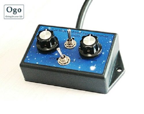
Recent (2025) developments in our hydrogen fuel system technology has shown even more significant improvements in fuel economy and engine torque after the addition of a MAF sensor enhancer module to our engines fitted with our latest 2025, as well as early model 2017 Hydrogen fuel systems.
These electronic fuel enhancer modules are relatively cheap and very easy to install / attach to the engine MAP ( Manifold air pressure / Boost Pressure sensor) Full documentation is provided with the modules that can even be used on vehicles without hydrogen fuel systems.
An electronic fuel enhancer module is a device that is designed to improve the fuel efficiency and performance of an internal combustion engine. These devices typically work by modifying the signal sent from the engine’s oxygen sensor to the engine control module (ECM), which in turn adjusts the fuel injection and ignition timing to optimize combustion.
The electronic fuel enhancer module intercepts the signal from the oxygen sensor and modifies it by altering the voltage or frequency of the signal. This modified signal is then sent to the ECM, which uses it to adjust the fuel injection and ignition timing to improve the engine’s performance and efficiency.
The electronic fuel enhancer module typically works by adjusting the air/fuel ratio to ensure that the engine is operating at its optimal level. By providing a more precise signal to the ECM, the module can improve fuel efficiency, increase horsepower, and reduce emissions.
It is important to note that the effectiveness of an electronic fuel enhancer module can vary depending on the specific engine and driving conditions. Some devices may not provide significant improvements in performance or fuel efficiency, while others may have a more noticeable impact.
Overall, an electronic fuel enhancer module is designed to modify the signal from the oxygen sensor to optimize engine performance and improve fuel efficiency. However, it is important to research and choose a reputable product that is compatible with your specific vehicle and driving habits.
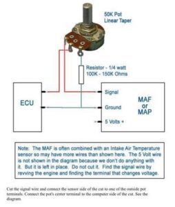
A MAP (Manifold Absolute Pressure) sensor enhancer is an electronic device used to modify the signal output of a MAP sensor in order to increase engine performance. The circuit diagram of a basic MAP sensor enhancer typically includes the following components:
Here is a basic circuit diagram of a MAP sensor enhancer:
MAP Sensor –> Capacitor –> Resistor –> Amplifier –> Potentiometer –> Output to ECM
Please note that the exact circuit diagram of a MAP sensor enhancer may vary depending on the specific application and the manufacturer of the device.
Views: 11
Monday, April 24, 2023
Brilliant Invention Gen 20 Hydrogen Generator ---update Feb 7... Full Story

Drop in oil price and Hydrogen. April 22 2020... Full Story
Hydrogen Fuel Systems Pty Ltd Producing hydrogen gas May... Full Story

Application of Hydrogen as Fuel Supplement in Internal Combustion... Full Story
An outlook of hydrogen as an automotive fuel February... Full Story
Payment Methods Partner:

© 2023 - Hydrogenfuelsystems pty ltd