Brilliant Invention Gen 20 Hydrogen Generator
Brilliant Invention Gen 20 Hydrogen Generator ---update Feb 7... Full Story
Perth, West Australia
High Current DC switches. Mechanical relays used to be the way to switch high currents; these days, we have a whole class of FETs available to do that job.
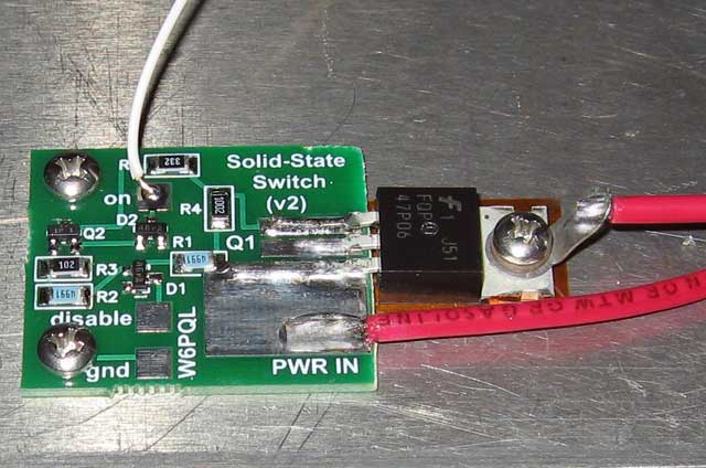
I use this small board to gate the power supply current to one of my solid-state amplifiers, but it can be used as a gate for almost anything requiring the switching of DC currents up to 100 amps.
With the FET shown here, this board is set up to switch 28 volts at up to 30 amps, and at that load, will drop only half a volt across the FET. When used to gate the power to one of the 23cm 150w amplifiers (10A or so), the loss across the switch is only about 2 tenths of a volt.
Consequently much less electrical energy is lost in the electronic components , leaving more electrical energy available to produce Hydrogen gas / chemical energy
This Post is a simple design that avoids the faulty and defective design used for common Hydrogen generator systems. Typically a PWM power supply is used for Hydrogen generators , but a PWM unit is designed for DC motor control circuits. A PWM is not for electrolysis circuits. Whats the difference you ask……. Good question.
A DC motor has inductive coils which produce a back voltage when operating and reduce their efficiency. BY having a pulse wave modulation system , high frequency DC pulses are produced. This avoids the Back voltage problem and making the DC motor efficiency increase. In an electrolysis circuit there is no such inductive back voltage to reduce the efficiency. Using a PWM unit simply introduces an electronic circuit that uses electrical energy , overheats and limits the efficiency of the hydrogen Generator circuit . SO AGAIN I HEAR YOU ASK , WHY ARE WE USING PWM POWER SUPPLIES. Its great that out ESP is switched on today
Good Question… simple answer. A PWM circuit is an easy control unit to use , especially by so called “EXPERTS in HHO”. Experts who have little more than a Primary school education , and specializing in finger painting. Am I arrogant, sometimes rude, opinionated, Educated, Multi skilled? Yes I am a Teacher with Multiple University degrees , a University Resaerch Scientist and Teacher? I AM an expert in Chemistry, Theoretical Physics, Chemical and Civil Engineering and Education. I know We need to effectively tackle the problem of Global warmng with “REAL” Science not make believe “witch doctor mumbo Jumbo”. My systems are patented and proven. This passage is all about effectively manufacturing Hydrogen and in particular effective power supply systems to produce it
Please read ahead in the following passage and learn how to provide power without wasting input energy. The MOSFET circuits shown can be easily “daisy chained” together in parallel to provide better regulated power. It does not overheat, does not waste energy as a high frequency pulsating supply and works in all conditions . Email me at glknox11@live.com if you have any more questions . Happy reading.
With minor component changes on the board, and the selection of a different FET, the switching of voltages and currents much higher than that can be achieved. Alternatively, additional FETs can be connected in parallel for higher currents, each one sharing the board connections. Configured like this, the FETs must be identical types, preferably from the same lot number.
For the newer 65v LDMOS amplifiers, I added a higher voltage version of this switch to the parts page, capable of handling up to 80v at 50 amps (this switch uses a 100v device.

To operate the switch, all that is required is grounding the ‘on’ port. Current at this port is only 5ma. Un-grounding this port turns the switch back off.
When used with a sequencer or an amplifier control board, this port should be connected to event 2 (so that the amplifier is switched on after the antenna relays have been switched at event 1).
An extra port is placed on the board to allow the switch to be disabled by an emergency signal (the ‘disable’ port). This port is typically handled by the “kill” function of a control board, which can signal an immediate overriding shutdown during a system fault condition. It does this by pulling the port low.
High Current DC switches. Another application using this extra port is the operation of a remote LNA and it’s bypass relay, which are typically energized by default. Connecting the “on” port to ground, and then the “disable” port to event 1 of a sequencer or control board will allow the LNA to remain on during receive, and then bypassed during the transmit cycle.
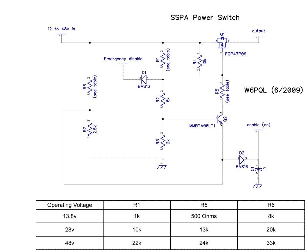
The table below the schematic lists the correct R5 values for 12v or 28v operation. Values for 2 different FETs are listed. The voltages shown are approximate ranges, and the ranges can overlap a bit. For example, the 12v configuration would be OK for 9 to 20v, and the 28v values would work well from 20 to about 36v.
High Current DC switches. The kit offered on the parts page (rev 3) is an upgrade to the one shown in the photo above, and can be set up for 12, 28 or 48 volts. The 48v optimization has a range of about 35 to at least 58v. The setup table for this version is shown below the schematic:

Views: 39
Saturday, December 29, 2018Brilliant Invention Gen 20 Hydrogen Generator ---update Feb 7... Full Story
Drop in oil price and Hydrogen. April 22 2020... Full Story
Effect of Water Vapor Injection on the Performance and... Full Story
Wide-Band-Instructions - HydrogenFuelSystems Click here Full Story
Narrow band Oxygen sensor instructions Click here for... Full Story
Payment Methods Partner:

© 2023 - Hydrogenfuelsystems pty ltd