Brilliant Invention Gen 20 Hydrogen Generator
Brilliant Invention Gen 20 Hydrogen Generator ---update Feb 7... Full Story
Perth, West Australia

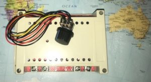
The Latest Design regulated Power supply has been designed and tested on our Patented Gen 10 Hydrogen generators with exceptional results as shown below

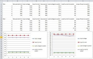
The Results of the regulated Power supply connected to a Gen 10 system operating for test period up to 720 minutes at input voltage of 13.8 volts and Input currents of 30 and 40 amp.. The output current were 1 amp lower than the input currents inn each case and , just as important , the load voltage only decreased by 0.4 volts. This is very important as the oxidation / reduction voltage of the 6 cells in series must not fall below 2.2 volts per cell.
The System voltage is always in excess of the Red/Ox voltage of water and therefore the gas production is always at its maximum.
This is crucial for any Hydrogen generator Power supply. Commonly available Power supplies waste 1.5 to 2 volts in the internal circuitry of the control unit and therefore the number of cells that can be used is reduced. This ,means that the volume of gas is reduced and the excess voltage / electrical energy is used to boil the water – you want hydrogen gas not steam.
The new Power supplies achieve the excellent performance by Using twelve Power MOSFETS that are voltage controlled , rather that Current controlled ( as used by the older less efficient systems) If you woul like to learn about Power MOSFET systems there are many good You tube videos available on these high efficiency units.
Power supplies are designed t control the electricity that is generating Hydrogen so that the load on the battery / alternator is not excessive, Excessive current flow increases the gas production but at a cost to loading on the engine.
By the power supply potentiometer to control the current flow can also place an unwanted load on the electronics on the PWM power supply itself.
The voltage of a cars battery / alternator is 13.2 volts . The electronic control unit is able to reduce the current flowing to the cells by reducing the output voltage of the power supply feeding to the cells . However the voltage applied to the electronic PWM Module remains 13.2 volts and the extra voltage is used up by the electronic components and Heat sink of the PWM unit.
This is a waste of electrical energy and causes the PWM module to heat up significantly.. Excess heat can damage / destroy the PWM power supply.
The solution to this situation is to-
By adjusting the current from say 35 amp down to the recommended 25 amp will waste 13.2 V x 10 A = 132.0 watt … this large power wastage must be disipated by the PWM heat sink and this makes the electronic circuit heat up.
Electronic circuit run best when cool
I hope thiis explains how to setup the Power PWM supply. If there is any misunderstanding please call me on 0403177183 glknox11@live.com
Gavan
Views: 7
Thursday, December 16, 2021Brilliant Invention Gen 20 Hydrogen Generator ---update Feb 7... Full Story
Drop in oil price and Hydrogen. April 22 2020... Full Story
Effect of Water Vapor Injection on the Performance and... Full Story
Wide-Band-Instructions - HydrogenFuelSystems Click here Full Story
Narrow band Oxygen sensor instructions Click here for... Full Story
Payment Methods Partner:

© 2023 - Hydrogenfuelsystems pty ltd