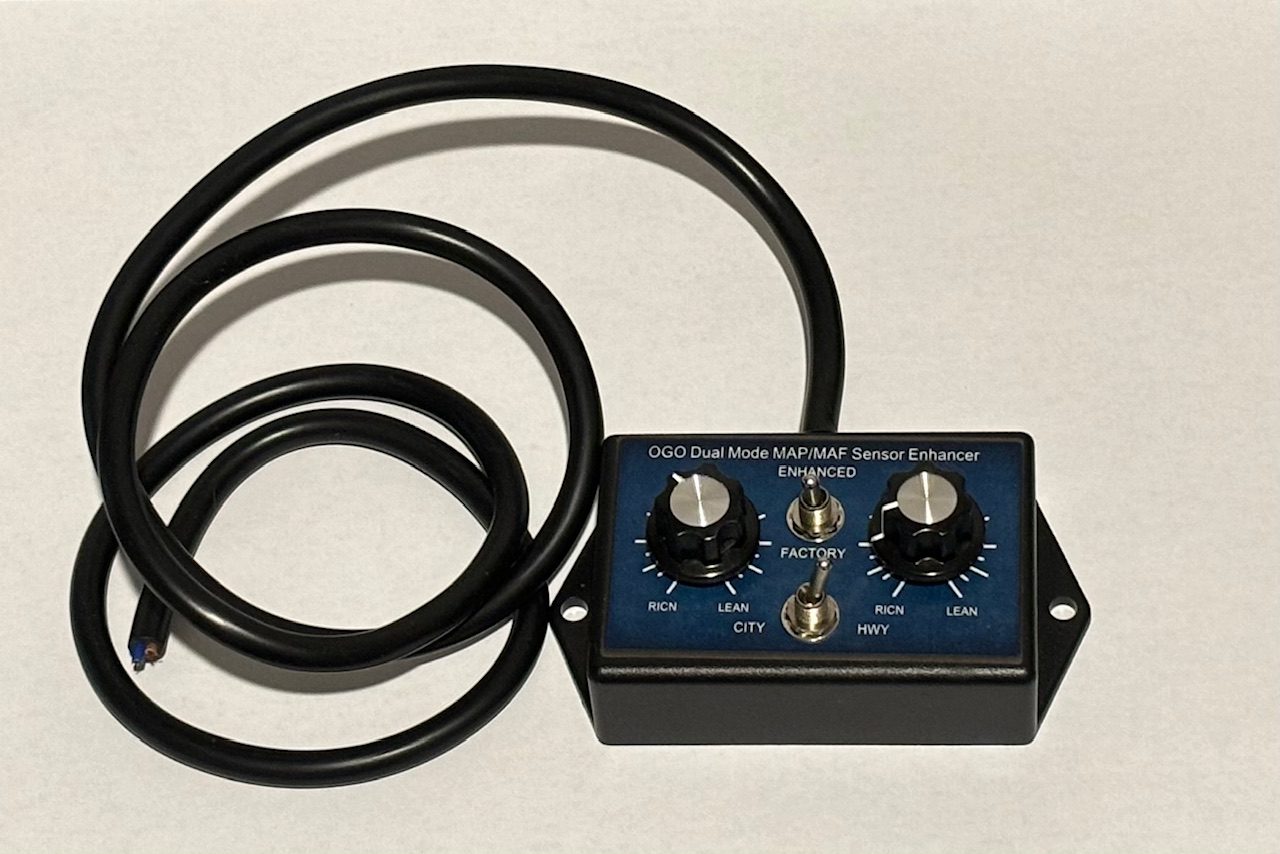
Brilliant Invention Gen 20 Hydrogen Generator
Brilliant Invention Gen 20 Hydrogen Generator Oxy-Hydrogen gas is... Full Story
Perth, West Australia


Engine coolant temperature sensors. Engine coolant temperature sensors (ECT) is a relatively simple sensor that monitors the internal temperature of the engine. Coolant inside the engine block and cylinder head(s) absorbs heat from the cylinders when the engine is running. The coolant sensor detects the change in temperature and signals the Powertrain Control Module (PCM) so it can tell if the engine is cold, warming up, at normal operating temperature or overheating.
The coolant sensor is extremely important because the sensor’s input to the PCM affects the operating strategy of the entire engine management system. That’s why the coolant sensor is often called the “master” sensor.
Many of the fuel, ignition, emissions and drivetrain functions handled by the PCM are affected by the engine’s operating temperature. A different operating strategy is used when the engine is cold than when it is warm. This is done to improve cold driveability, idle quality and emissions. Consequently, if the coolant sensor fails or is giving the PCM a false reading, it can upset a lot of things.
Input from the coolant sensor may be used by the PCM for any or all of the following control functions: Engine coolant temperature sensors.
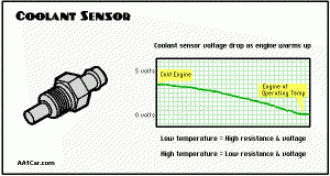
Most coolant sensors are “thermistors” that change resistance as the temperature of the coolant changes. Most are the “NTC” (Negative Temperature Coefficient) type where resistance drops as the temperature goes up. With this type of sensor, resistance is high when the engine is cold. As the engine warms up, the internal resistance of the sensor drops until it reaches a minimum value when the engine is at normal operating temperature.


Resistance specifications will vary depending on the application, so any sensor that does not read within its specified range should be replaced.
Coolant sensors have two wires (input and return). A 5-volt reference voltage signal is sent from the PCM to the sensor. The amount of resistance in the sensor reduces the voltage signal that then returns to the PCM. The PCM then calculates coolant temperature based on the voltage value of the return signal. This number can be displayed on a scan tool, and may also be used by the instrument panel cluster or driver information center to display the temperature reading of the coolant.
On some applications, a “dual range” coolant temperature sensor may be used. When the coolant reaches a certain temperature, the PCM changes the reference voltage to the sensor so it can read the coolant temperature with higher accuracy (higher resolution).
On some older vehicles, a different type of coolant sensor may be used. Some of these are essentially an on/off switch that opens or closes at a predetermined temperature. The sensor may be wired directly to a relay to turn the electric cooling fan on and off, or it may send a signal to a warning light on the instrument panel. These older coolant sensors are typically single wire sensors. On other older applications, a single wire variable resistor temperature sensor that grounds through the threads may be used to send a temperature signal to a gauge on the instrument panel. These are typically called temperature “senders” rather than sensors.
The coolant sensor is typically located near the thermostat housing in the intake manifold. On a few vehicles, the coolant sensor may be located in the cylinder head, or there may be two coolant sensors (one for each cylinder bank in a V6 or V8 engine) or one for the PCM and a second for the cooling fan.
The sensor is positioned so the tip will be in direct contact with the coolant. This is essential to produce a reliable signal. If the coolant level is low, it may prevent the coolant sensor from reading accurately.
Because of the coolant sensor’s central role in triggering so many engine functions, a faulty sensor (or sensor circuit) will often cause cold driveability and emission problems. A bad coolant sensor can also cause a noticeable increase in fuel consumption, and it may cause a vehicle to fail an emissions test if it prevents the engine management system from going into closed loop.
Keep in mind that many coolant sensor problems are more often due to wiring faults and loose or corroded connectors than failure of the sensor itself.
The coolant sensor’s impact on the engine management system, cold driveability, emissions and fuel economy can also be influenced by the thermostat. If the thermostat is stuck open, the engine will be slow to warm up and the coolant sensor will read low. Or, if someone installed the wrong thermostat for the application or removed the thermostat altogether, it will prevent the engine from reaching normal operating temperature and cause the coolant sensor to read low.
A faulty coolant sensor may also cause the engine to overheat if it fails to energize the cooling fan relay when the engine gets hot.
A faulty coolant sensor may also cause inaccurate coolant temperature gauge readings on the instrument panel.
On 1996 and newer vehicles with OBD II onboard diagnostic systems, a faulty coolant sensor may prevent some of the system monitors from running. This will prevent the vehicle from passing an OBD II emissions test because the test can’t be done unless all the required system monitors have run and passed.
The OBD II system should catch the fault, turn on the Check Engine Light or Malfunction Indicator Lamp (MIL), and set one of the following diagnostic trouble codes:
P0115….Engine Coolant Temperature Circuit
P0116….Engine Coolant Temperature Circuit Range/Performance
P0117….Engine Coolant Temperature Circuit Low Input
P0118….Engine Coolant Temperature Circuit High Input
P0119….Engine Coolant Temperature Circuit Intermittent
On older pre-OBD II vehicles, the Check Engine light may come on if the coolant sensor is shorted, open or is reading out of range. GM coolant sensor codes include codes 14 & 15, Ford codes are 21, 51 & 81, and Chrysler codes are 17 & 22.
A visual inspection of the coolant sensor will sometimes reveal a problem such as severe corrosion around the terminal, a crack in the sensor, or coolant leaks around the sensor. But in most cases, the only way to know if the coolant sensor is good or bad is to measure its resistance and voltage readings.
On vehicle systems that provide direct access to sensor data with a scan tool, the coolant sensor’s output can usually be displayed in degrees Centigrade (C) or Fahrenheit (F). The coolant sensor should read low (or ambient temperature) when the engine is cold, and high (around 200 degrees) when the engine is hot. No change in the reading or a reading that obviously does not match engine temperature would indicate a faulty sensor or a wiring problem.
The internal resistance of a coolant sensor can also be checked with an ohmmeter or DVOM (digital volt ohm meter) and compared to specifications. If the sensor is open, shorted or reads out of range, it must be replaced.
If the resistance of a coolant sensor is within specifications and changes as engine temperature changes, but the engine is not going into closed loop, the fault is in the wiring or PCM. Further diagnosis will be needed to isolate the problem before any parts are replaced.
One trick here is to use a sensor simulator tool to feed a simulated temperature reading through the sensor’s wiring harness to the PCM. If the wiring continuity is good but the PCM fails to go into closed loop when you send it a “hot coolant” signal, the problem is in the PCM.
You can also use a voltmeter or digital storage oscilloscope (DSO) to check the sensor’s output. Specs vary, but generally a cold coolant sensor will read somewhere around 3 volts. As the engine warms up and reaches operating temperature, the voltage drop should gradually decrease down to about 1.2 to 0.5 volts. If you’re using a scope to display the voltage signal, you should get a trace that gradually slopes from 3 volts down to 1.2 to 0.5 volts in three to five minutes (or however long it normally takes the engine to reach normal operating temperature).
If the voltage drop across the coolant sensor reads at or near 5 volts, it means the sensor is open or it has lost its ground connection. If the voltage is close to zero, the sensor is shorted or it has lost its reference voltage.
When working on 1985 and up Chrysler products, watch out for a sudden voltage increase as the engine warms up. This is normal and is produced by a 1000 ohm resistor that switches into the coolant sensor circuit when the sensor’s voltage drops to about 1.25 volts. This causes the voltage to jump back up to about 3.7 volts, where it again continues to drop until it reaches a fully warmed up value of about 2.0 volts.
Sometimes a coolant sensor will suddenly go open or short when it reaches a certain temperature. If your voltmeter has a “minimum/maximum” function, you can catch sudden voltage fluctuations while the sensor is warming up. If you are viewing the voltage pattern on a scope, a short will appear as a sudden drop or dip in the trace to zero volts. An open would make the trace jump up to the VRef voltage line (5 volts).
If the coolant sensor reads normally when cold (high resistance and 3 or more volts), but never seems to reach normal temperature it could be telling the truth! An open thermostat or the wrong thermostat may be preventing the coolant from reaching its normal operating temperature.
Most coolant sensors are not replaced unless they have failed. A coolant sensor that is shorted, open or reading out of range obviously can’t provide a reliable temperature signal and must be replaced for the engine management system to function properly. But many experts also recommend installing a new coolant sensor if you are replacing or rebuilding an engine. Why? Because coolant sensors can deteriorate with age and may not read as accurately as they did when they were new. Installing a new sensor can eliminate a lot of potential problems down the road.
It is also a good idea to replace the coolant sensor and thermostat if the engine has experienced a case of severe overheating. Abnormally high engine temperatures can damage these components and may cause them to misbehave or fail prematurely.
Replacing a coolant sensor requires draining some of the coolant from the cooling system. You do not have to drain the entire radiator. Just open the drain valve and let out enough coolant so the coolant level in the engine is below the sensor.
This would be a good to check the condition of the coolant, and to replace it if the coolant is more than three years old (conventional coolant) or five years old (long life coolant). A coolant change and a flush would also be a good idea if the coolant shows any signs of contamination.
The threads on the coolant sensor may be pre-coated with sealer to prevent coolant leaks. Tighten the sensor carefully to prevent damage.
Once the new sensor has been installed, you can refill the cooling system. Make sure all the air is out of the cooling system. Air trapped under the thermostat may cause the engine to overheat or the coolant sensor to not read correctly.
www.hydrogenfuelsystems.com.au
Gavan Knox
BSc (physics), BSc (chemisty), BEng (Civil), BEd (Physics/Maths),
glknox11@live.com
0403177183
Brilliant Invention Gen 20 Hydrogen Generator Oxy-Hydrogen gas is... Full Story
Drop in oil price and Hydrogen. April 22 2020... Full Story
Adjustable Power Supply Adjustable Power Supply 0-48V 60A |... Full Story
MAP / MAF engine sensor operation and engine efficiency-... Full Story
THE ELECTROLYSIS OF WATER TO GENERATE H2 march 26... Full Story
Payment Methods Partner:


© 2023 - Hydrogenfuelsystems pty ltd