Brilliant Invention Gen 20 Hydrogen Generator July 2 2026
Brilliant Invention Gen 20 Hydrogen Generator ---(update Feb 7... Full Story
Perth, West Australia


by Gavan Knox. May 24 2026
call Whats App +61 403177183
Electrolysis works by passing a DC current through water containing an electrolyte. At the cathode, water gains electrons and forms hydrogen gas. At the anode, water loses electrons and forms oxygen gas. The overall reaction is:
How the process works (step‑by‑step)
Pure water is a poor conductor, so electrolysis usually requires:
This allows current to flow.
A DC power supply is connected to two electrodes:
The minimum theoretical voltage is 1.23 V, but real systems need 1.6–2.2 V due to losses of internal to internal resistance / reactance of the water
⚗️ 3. Chemical reactions at each electrode
At the cathode (negative electrode)
Water molecules gain electrons:— an reduction reaction
This produces hydrogen gas.
At the anode (positive electrode)
Water molecules lose electrons: – a oxidation reaction
This produces oxygen gas.
🌬️ 4. Gas collection
Because hydrogen and oxygen form at different electrodes, they can be collected separately: this is theoretical production as in a science laboratory .
In a vehicle this is not practical without complex separation techniques.
In a vehicle , generator or generator assembly a mixture of both gases are collected ( not stored ) and used immediately by the IC to perform fuel saving and emissions,
In PEM systems, the membrane keeps the gases separated with very high purity.
📊 Gas ratio
Electrolysis always produces gases in a 2:1 ratio:
This matches the molecular structure of water (H₂O).
⚡ Efficiency and energy use
Typical efficiencies:
Higher efficiency = less electrical energy needed per kg of hydrogen.
🧪 Types of electrolysis systems
| System | Electrolyte | Pros | Cons |
| Alkaline (KOH/NaOH) | Liquid alkaline solution | Cheap, durable
Electrodes are protected from electrolysis in an alkaline solution |
Lower purity, slower response |
| PEM (Proton Exchange Membrane) | Solid polymer membrane | High purity H₂, compact, fast
Expensive to produce and maintain |
Expensive catalysts |
| HHO / Dry cell | KOH/NaOH | Simple, DIY-friendly but problems with electrode stability / corrosion | Low efficiency, mixed gas output |
🔥 Why this matters for hydrogen fuel systems
For your hydrogen‑assist kits:
Why PEM produces more usable hydrogen per watt compared to typical HHO cells,
The short answer: PEM produces more usable hydrogen per watt because almost all of the electrical energy goes into splitting water — not fighting heat, resistance, or side‑reactions like in HHO cells.
Here’s the deeper, engineering‑level breakdown tailored to the systems you work with.
⚡ 1. Internal resistance: PEM is extremely low, HHO cells are high
A PEM membrane is a solid polymer proton conductor with very low ionic resistance. An HHO cell uses liquid electrolyte + metal plates, which introduces:
Every extra ohm wastes watts as heat instead of hydrogen.
Result: PEM converts more of each watt into actual electrochemical work.
⚡ 2. PEM runs at high current density without overheating
PEM stacks are designed to operate at 1–3 A/cm² efficiently. HHO cells typically struggle above 0.2–0.4 A/cm² before:
So even if both systems draw the same amps, the PEM stack stays in its efficient zone while HHO cells fall off a cliff.
⚡ 3. No mixed gases → no recombination losses
HHO cells produce mixed steam, H₂ + O₂ in the same chamber. This causes:
PEM separates gases by design:
This alone increases usable hydrogen per watt.
⚡ 4. PEM has catalytic electrodes, HHO plates do not
PEM uses platinum‑group catalysts that dramatically reduce activation energy.
HHO cells rely on:
These are not catalytic, so more voltage is wasted overcoming activation losses.
PEM typically operates at 1.6–2.0 V per cell. HHO cells often require 2.2–2.8 V per cell once heated.
My HFS systems are operating at levels close to that of a PEM systems . WE have developed a new patented alloy anode together with the stainless steel 316L cathode that operates at a reduced Eo value to have a lowetr operating voltage per cell and waste less energy as heat. This innovation is patented / patent pending and will be released for commercial applications as soon as the patent is granted.
Lower voltage per cell = more hydrogen per watt.
⚡ 5. PEM has no electrolyte contamination or parasitic reactions
HHO cells suffer from:
PEM uses pure water, so:
This stability increases watt‑to‑hydrogen efficiency.
⚡ 6. PEM produces usable hydrogen, HHO produces a diluted gas
This is the part most people miss.
HHO gas is:
PEM produces:
So even if the raw volume per amp is similar, the usable hydrogen from PEM is far higher.
🎯 Bottom line
PEM wins because it wastes far less energy.
| Factor | PEM | HHO Cell |
| Internal resistance | Very low | High |
| Heat losses | Low | High |
| Gas purity | 99.999% H₂ | Mixed HHO |
| Voltage per cell | 1.6–2.0 V | 2.2–2.8 V |
| Current density | High | Low |
| Side reactions | None | Many |
| Efficiency | 60–70% | 20–40% |
So per watt, PEM gives you more hydrogen, cleaner hydrogen, and more usable hydrogen.
have developed 4 models of Hydrogen system for engines of
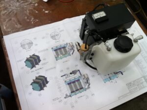


The Hydrogen gas produced by these systems is collected in the recycling water tanks and then passed into the engine air-intake ahead of the turbo charger
The Gas simply increases the efficiency of the combustion process by burning all the fuel injected at close to TDC.
Wasting up to half the fuel at the lower part of the power stroke and wasting it out the exhaust is of no use to the engine … the Power of combustion cant be used to power the engine to reach its required speed when burnt at the bottom of the engine stroke.
Hydrogen massively speeds combustion so less throttle is used, less fuel is injected, required power is produced and gas emissions are reduced.


These systems are being used internationally through my JV partners ( Singapore and India) FOR cars , trucks, generators, farming, marine applications etc
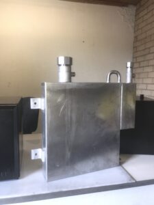
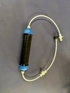 Water Resin Filter. Produce laboratory grade Pure water
Water resin filter produces Pure water out of polluted ground water — lasts 5000 liters before needing to replace the cartridge … Purifies 5 liters per hour


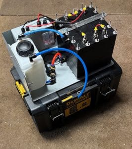
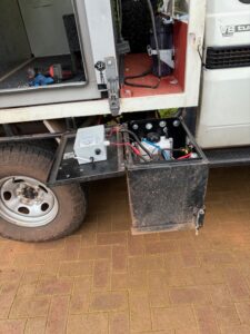
Gen 15 hydrogen system on campervan
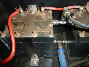

Photos ABOVE show a 16 litre volvo of Ian uses twin Gen 20 systems and a modified tank system to store his electrolyte
25 to 30% savings


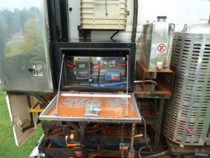
J#### – a farmer in SW Wa has a gen 15 system on his Nissen mounted into a steel box hinged under his Nissen tray

K##### a Keen surfer having spent his lige working his farm in N qld … divorce and now lives week to week surfing around Australia…. Promoting my systems and getting commissions for sales…a bit lonely but living the Dream he says

Work Vehicle in Perth Gen 15 system fitted out by C##### …. Attempted to copy and to BREACH My PATENT… Illegal – legal action will follow
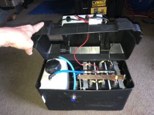
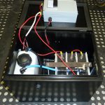
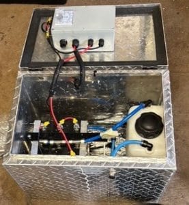
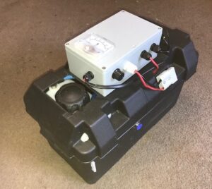
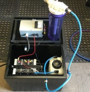
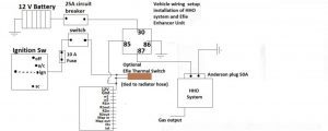
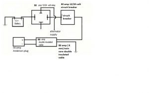
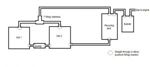
Photos of connection of HFS systems
Basic structure fo connecti0ons – wiring and tubing for the hydrogen fuel system
the system recycles the electrolyte —– each liter of water produced 1440 litres of hydrogen gas over a 6 hour period
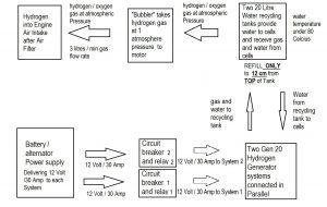
The tank size can be changed to sut your needs and how the gas production can be increased by altering the control dial on the power supply , to suit your needs
L#### is a keen WA gold prospector and with the Hydrogen system can travel further between refills …. Which is crucial in outback West Australia where stations can be many hundreds of miles apart

My last Photo of this presentation is that of my second youngest daughter — my princess…..The Most important reason I invented my hydrogen fuel system is to give my daughter and the rest of the world a chance to live in a world where global warming is not what they have to try and live under

A few years ago (17 now ) and my increased sales internationally shows my systems are being used by governments like India …. We have hope
Views: 25
Sunday, May 24, 2026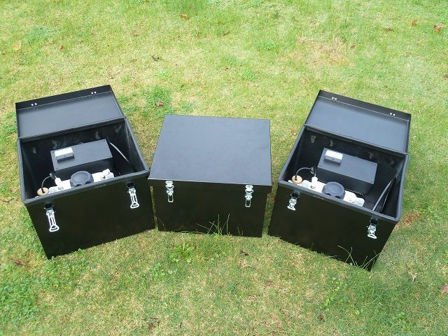
Brilliant Invention Gen 20 Hydrogen Generator ---(update Feb 7... Full Story

by Gavan Knox HFS whats app +61 403177183 gavan@hfuel.com.au... Full Story
Hho Kit Wiring Diagram - July 8 by Gavan... Full Story
Hydrogen Generator Installation Guide - july 7 by Gavan... Full Story
Hydrogen Kit Emissions Reduction Explained - July 6 by... Full Story
Payment Methods Partner:

© 2023 - Hydrogenfuelsystems pty ltd