Brilliant Invention Gen 20 Hydrogen Generator July 2 2026
Brilliant Invention Gen 20 Hydrogen Generator ---(update Feb 7... Full Story
Perth, West Australia





by Gavan Knox MSc, BSc, BEd, Inventor
WhatsApp call +61 403177183
contact gavan@hfuel.com.au
https://hydrogenfuelsystems.com.au
How to Install HHO Dry Cell Kits Properly – Aug 10. A poor HHO installation costs more than time. Loose wiring, a badly placed reservoir or an unprotected hose can turn a fuel-saving upgrade into an avoidable breakdown. Knowing how to install hho dry cell equipment correctly means treating it like any serious engine accessory: mount it securely, wire it properly, keep the gas path tight and test every connection before the vehicle goes back on the road.
An HHO dry cell system is designed to generate hydrogen and oxygen gas on demand, then introduce that gas into the engine intake to support cleaner, more complete combustion. The potential pay-off is lower fuel use, improved throttle response and reduced emissions, but the result depends heavily on correct sizing, sound installation and realistic vehicle tuning.

Before lifting a spanner, confirm the generator size suits the engine capacity and duty cycle. A commuter car, a loaded ute, a 4WD towing a van, a diesel truck and a standby generator do not place the same demand on an HHO system. An undersized unit may limit results; an oversized or poorly controlled setup can create unnecessary electrical load and maintenance.
Read the supplied wiring diagram and installation documentation from start to finish. Identify where the dry cell, reservoir, bubbler, relay, fuse, hoses and electrical connections will sit before drilling anything. The best installation is compact, accessible and protected from heat, vibration and road spray.
Check local modification, registration and insurance requirements before proceeding. Do not disable, remove or bypass factory emissions equipment, sensors or safety systems. Late-model vehicles may need application-specific tuning or electronic controls to work as intended, particularly where sensitive engine management systems are involved.
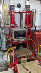
The dry cell needs a strong mounting point in the engine bay or another protected location with adequate ventilation. It must remain upright, clear of moving belts, fans, steering components and exhaust heat. Avoid mounting it directly above sensitive electrical equipment or where a small leak could run onto painted panels, wiring looms or the alternator.
The electrolyte reservoir should be mounted higher than, or in the position specified for, the dry cell so filling and fluid movement work correctly. Keep it accessible. If topping up the reservoir requires removing half the engine bay, routine servicing will get ignored.
Install the bubbler or safety bottle in the gas line between the cell and the engine intake. This component is not optional. It provides a water barrier and an additional layer of flashback protection. Position it upright, away from exhaust heat, and where it can be checked without dismantling other components.

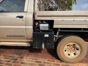
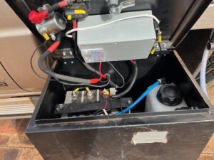

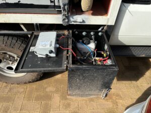
Disconnect the negative battery terminal before any electrical work. HHO systems operate in an engine bay containing fuel, heat, electrical current and rotating parts. Work in a well-ventilated area, keep sparks and flames away, and wear eye protection and chemical-resistant gloves when handling electrolyte.
Secure the dry cell using the supplied brackets or a purpose-built mount. Use quality fasteners, nyloc nuts or thread locking where appropriate, and ensure no sharp edge can rub through a hose or cable. A cell that vibrates excessively will eventually damage fittings, fatigue brackets and create leaks.
Run hoses with smooth bends and enough slack for normal engine movement. Keep them well away from the exhaust manifold, turbocharger, belts and fan. Use proper hose clamps at every fitting. Do not rely on cable ties alone to hold a gas hose onto a barb.
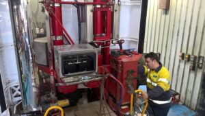
The intake connection is normally made into a suitable point after the air filter and before the intake manifold, according to the supplied application instructions. Drill only after checking both sides of the chosen section. You do not want metal or plastic swarf entering the intake tract, and you do not want to drill into a sensor housing, intercooler pipe seam or a component that cannot be safely resealed.
After drilling, remove all debris, fit the hose barb or bulkhead fitting, and seal it correctly. The fitting must be airtight. Even a minor intake leak can affect engine behaviour, trigger fault codes or reduce the effectiveness of the system.
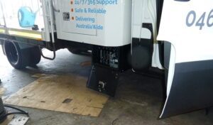
The dry cell should never be connected as an uncontrolled, permanent battery load. It needs a fused power supply and relay arrangement so it runs only when the engine is operating or the ignition circuit is active, as specified by the kit design.
Mount the relay and fuse holder in a dry, serviceable location. Place the fuse as close to the battery positive terminal as practical to protect the cable length. Route positive cable through split conduit where it passes near metal edges, and use grommets whenever wiring travels through a panel.
Connect the main power feed using correctly sized cable, secure terminals and clean connection points. A weak earth is one of the fastest ways to create inconsistent current draw and poor HHO output. Run the earth lead to a clean, solid chassis or engine earth point, removing paint or corrosion where necessary and protecting the finished connection from moisture.
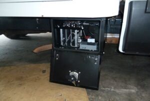


Use an ignition-switched trigger wire for the relay where required. Do not tap randomly into a critical ECU, airbag, ABS or sensor circuit. If you are uncertain which circuit is suitable, use a test light or multimeter and follow the kit instructions. For commercial vehicles, marine engines and generators, it may be wiser to have the final electrical connection completed by a qualified auto electrician.
Before reconnecting the battery, inspect the entire cable route. Every wire should be clipped, supported and clear of heat and moving parts. A neat installation is not cosmetic. It is evidence that the system is unlikely to chafe, short out or fail when the vehicle is working hard on rough roads.
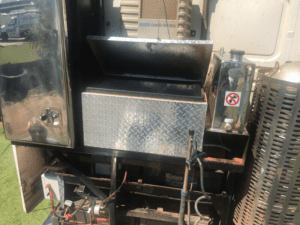
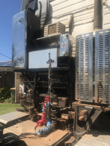
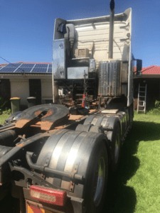

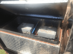
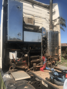
Use only the electrolyte type and concentration recommended for your dry cell. Many systems use potassium hydroxide, which is highly caustic. Never treat it like ordinary workshop fluid. Add chemical to distilled water slowly in a suitable container, never water into chemical, and follow the handling directions supplied with the product.
Do not overfill the reservoir. Leave the required expansion space and make sure caps, fittings and level lines are correctly fitted. Wipe away any spills immediately with plenty of water, then inspect surrounding components for residue. Electrolyte contamination can damage paint, aluminium parts and electrical terminals.
Once filled, check every cap, hose fitting and cell connection. The fluid circuit must be sealed and the gas path must remain unrestricted. Kinked hose, loose caps and incorrect fluid level are basic faults that can make a good system perform badly.

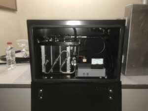
Reconnect the battery and start the engine. Confirm the relay switches the system on only under the intended conditions. Check for correct current draw with a multimeter or clamp meter, using the specifications supplied for the kit. Excessive current can indicate incorrect electrolyte concentration, a wiring fault or an issue within the cell.
Inspect for gas and fluid leaks while the system operates. A light soapy-water test around external gas fittings can help identify leaks, but keep liquids away from exposed electrical terminals. Check that the bubbler is functioning correctly and that there is no electrolyte travelling into the intake hose.
Let the engine reach operating temperature, then recheck hose routing, wiring security and fluid level. Listen for intake leaks and watch for warning lights, rough idle or unusual engine behaviour. If something is not right, stop and fix the cause rather than continuing to drive and hoping it settles down.

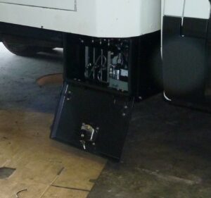
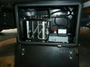
Fuel savings are not proved by one short trip around the block. Establish a baseline using the same route, load, tyre pressures and driving style where possible. For fleet vehicles, record litres used, kilometres travelled, payload, idle time and driver conditions across several fill cycles.
This is where disciplined operators separate a genuine operating-cost improvement from guesswork. Hydrogen Fuel Systems equipment should be installed, monitored and maintained as a working engine system, not as a fit-and-forget gadget. Keep records of current draw, electrolyte top-ups and fuel use so you can see whether the setup is delivering value in your application.


A properly mounted dry cell, protected wiring run and sealed intake connection give the system its best chance to perform under real Australian conditions. Take the extra hour to do the final checks now – it is far cheaper than repairing an avoidable fault later.



by Gavan Knox MSc, BSc, BEd.
WhatsApp call +61 403177183
contact gavan@hfuel.com.au
https://hydrogenfuelsystems.com.au
Brilliant Invention Gen 20 Hydrogen Generator ---(update Feb 7... Full Story

by Gavan Knox HFS whats app +61 403177183 gavan@hfuel.com.au... Full Story

Best Vehicles for HHO Upgrades in Australia - Oct... Full Story

Fuel Economy Methodology That Produces Real Numbers - oct... Full Story

Can HHO Improve Towing Economy? Facts That Matter -... Full Story
Payment Methods Partner:

© 2023 - Hydrogenfuelsystems pty ltd