Brilliant Invention Gen 20 Hydrogen Generator July 2 2026
Brilliant Invention Gen 20 Hydrogen Generator ---(update Feb 7... Full Story
Perth, West Australia




by Gavan Knox MSc, BSc, BEd.
WhatsApp call +61 403177183
contact gavan@hfuel.com.au
https://hydrogenfuelsystems.com.au
A bad electrical install will kill a good hydrogen system faster than almost anything else. If you are searching for an hho kit wiring diagram, you are usually at the point where the plates, bubbler and hose routing make sense, but the wiring still feels like the part that can cost you time, output and reliability.
That concern is valid. An HHO kit does not reward guesswork. Wire it properly and you get stable current, cleaner operation and the best chance of real-world fuel savings and performance gains. Wire it badly and you can end up with voltage drop, blown fuses, overheated cables, relay issues and inconsistent gas production.
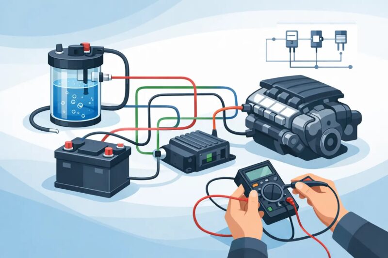
A proper wiring diagram is not just a picture showing where the red wire goes. It has one job – deliver controlled power from the vehicle to the HHO cell safely and consistently.
That means the battery feed must be protected by a fuse, the relay must switch the main load cleanly, the ignition source must trigger the relay only when the engine is meant to run, and the earth path must be solid enough to carry current without resistance stealing performance. If your system uses a current controller, PWM or other power management device, the diagram also needs to show exactly where that component sits in the circuit. Put it in the wrong place and your numbers on paper will not match what the cell is really seeing.
For owners chasing lower diesel costs, better throttle response or reduced smoke, this matters more than people think. HHO output depends on electrical input. Weak wiring means weak production.
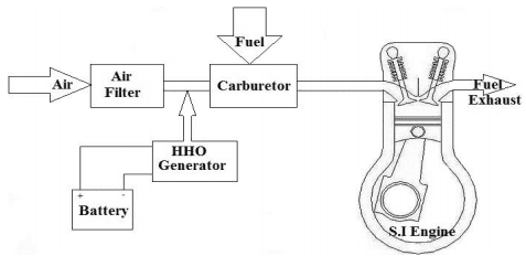
Most vehicle installs follow the same core pattern. Battery positive runs to an inline fuse. From the fuse, power goes to the relay or controller, depending on system design. The relay is triggered by an ignition-switched source so the HHO system turns on with the vehicle, not while it is parked. From there, power feeds the cell. The negative side returns to a clean chassis earth or directly to battery negative, depending on the application and current draw.
In plain terms, the main circuit normally looks like this:
The trigger side looks like this:
The return side looks like this:

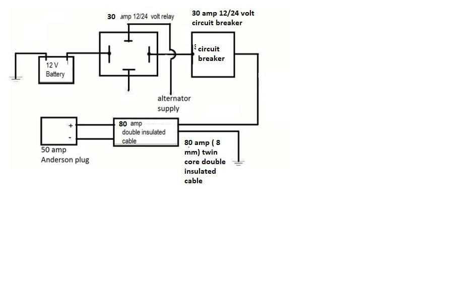

A Solenoid relay is not optional on a serious install. It protects the ignition circuit from carrying the full load of the HHO cell and gives you a cleaner, safer switching method.
Without a relay, some installers try to run operating current through a small switched source. That is where heat, voltage loss and premature failure start. A proper automotive relay lets the battery do the heavy lifting while the ignition feed simply turns the system on and off.

The 40 amp or 30 amp manual reset circuit breaker should sit as close to the battery positive as practical. That way, if the cable shorts anywhere downstream, the circuit is protected.
Putting the fuse halfway down the line is a mistake. The unfused section between battery and fuse is still live and still capable of causing damage. Good diagrams make this clear because safety is not separate from performance. It is part of it.
This system must be installed by a qualified Austo electrician / mechanic.
A lot of vehicle owners can handle tools but still hate electrical symbols. Fair enough. Most diagrams become easier once you stop looking at them as abstract lines and start reading them as a power path.
Start at the battery positive and follow the current. Ask what protects it, what switches it, what controls it and where it ends up. Then trace the return path back to earth or battery negative. If a controller is included, confirm whether it sits before the cell on the positive side. If there is a water level sensor, dash switch or warning light, treat those as separate support circuits, not part of the main high-current path unless the documentation says otherwise.
If a diagram is unclear about wire gauge, that is a red flag. Current draw and cable size go together. Too thin and the wire becomes a restriction. That means heat, reduced output and wasted potential.
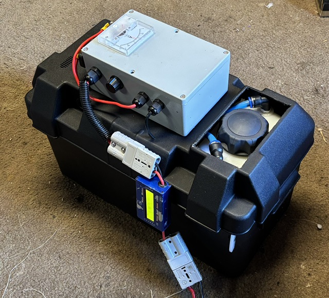
The first mistake is undersized cable. 8 mm (8 Band S double insulated) cable is required for this system. This one shows up constantly, especially when an installer uses whatever automotive wire is already on the shelf. HHO systems draw current continuously, and cable needs to match that load. A system that looks connected can still underperform badly if the cable cannot support proper current flow.
The second mistake is poor earthing. Paint, rust, loose bolts and dirty chassis points all add resistance. You might still get operation, but not stable operation. If your cell output varies or current readings drift, earth quality is one of the first things to check.
The third mistake is taking the trigger feed from the wrong source. You want an ignition-switched signal that behaves consistently. Some modern vehicles have circuits that remain active briefly after shutdown or behave differently under load. If the relay does not switch exactly when it should, the system can stay live when you do not want it to.
The fourth mistake is bypassing current control. More current is not automatically better. The right diagram keeps the system in its intended operating range. Overdriving a cell can increase heat, stress components and shorten service life. Real performance comes from controlled production, not brute-force wiring.
This is where generic diagrams fall short. A small petrol car, a diesel ute, a long-haul truck and a generator do not all want the same cable run or mounting strategy.
In a compact engine bay, short cable runs may make battery-to-relay-to-cell straightforward. In a larger 4WD or truck, cable length becomes a bigger factor, so voltage drop deserves more attention. Marine and generator installs often demand extra care around vibration, moisture exposure and service access. 8mm, 8 Band S , double insulated cable is the minimum to be used on all systems. Large trucks with greater distance for the current to flow cqn use larger cable size.
That is why a useful HHO kit wiring diagram should be treated as a starting framework, then adjusted to the vehicle. The principle stays the same. The execution changes with the job.
Bigger systems need more respect. If you are stepping up from a smaller generator setup to a larger unit designed for higher-consumption engines, current demand will usually increase as well.
That affects fuse rating, relay specification, cable size and heat management. A wiring layout that survives on a small passenger vehicle may be inadequate on a harder-working diesel platform. This is one reason proven, application-specific documentation matters. The electrical side has to match the mechanical promise of the kit.
Before first startup, check every termination by hand. Tug-test crimped connections. Confirm fuse rating. Verify relay terminal numbers. Make sure positive and negative at the cell are exactly where they should be. Check for cable contact with sharp edges, hot surfaces and moving parts.
Then confirm that the system only receives main power when the ignition trigger is active. If the relay clicks correctly but the cell does not receive full voltage, start measuring for drop across each stage of the circuit. That is how you find bad joins, weak earths and undersized cable quickly.
Do not judge performance by sound or bubbles alone. If you want reliable output, measure voltage and current under normal running conditions. Numbers tell the truth.
Some installs include extras such as PWMs, EFIE-related support hardware on older applications, level switches, indicator lamps or isolation switches. Once those extras enter the job, a one-size-fits-all sketch is no longer enough.
At that point, proper documentation becomes part of the product value. Clear terminal identification, recommended wire gauge, fuse size, relay type and application notes save time and prevent expensive mistakes. For a commercial operator or owner-driver, that matters. Downtime costs more than doing the wiring properly the first time.
This is also where tested systems separate themselves from backyard experiments. A serious supplier should provide wiring guidance that reflects actual vehicle use, not theory alone. Hydrogen Fuel Systems has built its reputation around that practical, proven approach because buyers want results they can install, not ideas they have to invent on the workshop floor.
People often treat wiring as the boring part of an HHO install. It is not. It is the control point for the whole system. Good electrical design protects the vehicle, supports stable gas production and gives the cell the conditions it needs to perform.
If you are fitting an HHO kit to cut fuel costs on a work ute, improve diesel response in a 4WD, or help a generator run cleaner and harder, the wiring diagram is not a side note. It is the difference between a system that merely powers up and one that actually delivers.
Take the extra time to match the diagram to the vehicle, size the wiring properly and verify every connection. The gains you want from hydrogen enhancement start with disciplined installation, and the electrical side is where that discipline shows.
call Gavan on +61 403177183 – on WhatsApp or 0403177183 to clarify any points in this Post.
Contact Gavan through email gavan@hfuel.com.au or gavan@hfuel.com.au or through this website HERE
Wednesday, July 8, 2026
Brilliant Invention Gen 20 Hydrogen Generator ---(update Feb 7... Full Story

by Gavan Knox HFS whats app +61 403177183 gavan@hfuel.com.au... Full Story

Fuel Economy Methodology That Produces Real Numbers - oct... Full Story

Can HHO Improve Towing Economy? Facts That Matter -... Full Story

HHO Versus Additives: What Actually Pays Back? - Oct.... Full Story
Payment Methods Partner:

© 2023 - Hydrogenfuelsystems pty ltd