Brilliant Invention Gen 20 Hydrogen Generator July 2 2026
Brilliant Invention Gen 20 Hydrogen Generator ---(update Feb 7... Full Story


by Gavan Knox MSc, BSc, BEd, Inventor
WhatsApp call +61 403177183
contact gavan@hfuel.com.au
https://hydrogenfuelsystems.com.au
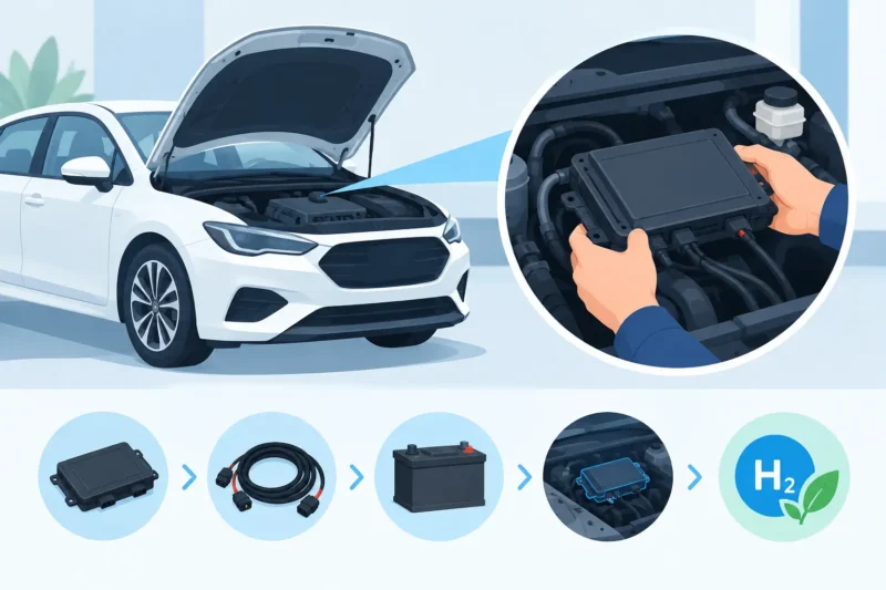
How to Install a Hydrogen Controller in Your Vehicle – Oct 24. A hydrogen controller is the part that decides whether your HHO system delivers controlled support or becomes another unreliable under-bonnet accessory. If you are asking how to install hydrogen controller wiring correctly, the answer starts with one rule: fit it as a protected, switched electrical circuit, not as a quick wire-in job. Get the controller, relay, fuse and cable sizing right and your hydrogen generator can operate consistently with the engine.
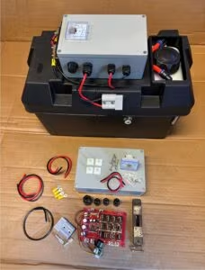
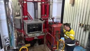
For a ute, truck, 4WD, marine engine or generator that works hard, that consistency matters. Current that is too low limits gas production. Current that is too high can overheat wiring, consume excess electrolyte and shorten component life. The controller protects the system while giving you a practical way to set output for the engine and generator size.
A hydrogen controller regulates the electrical power supplied to the hydrogen generator. Depending on the system design, it may be a pulse-width modulation controller, often called PWM, or another purpose-built current-control unit. Its job is to manage amperage rather than simply feed the cell unrestricted battery voltage.
That matters because hydrogen generation follows electrical input. More current generally means more gas production, but it also creates more heat. The best setting is not automatically the highest setting. It is the setting that provides stable production without pushing the cell, wiring or alternator beyond their intended operating range.
On a correctly installed HHO kit, the controller should only operate when the engine is running or when an approved ignition-switched supply is active. It must not draw power continuously while the vehicle is parked. A flat starting battery is not a fuel-saving upgrade.
Confirm your kit’s wiring diagram before cutting, crimping or connecting anything. Hydrogen generator systems vary by cell size, vehicle voltage, relay design and current requirement. A Gen 10 setup on a small passenger vehicle does not necessarily use the same wiring layout or controller setting as a Gen 25 system supporting a larger diesel application.
Choose a mounting point that is dry, secure and away from direct exhaust heat, moving belts, steering components and sharp edges. Under-bonnet temperatures are severe, particularly in Australian summers and in vehicles that tow, work off-road or spend long hours idling. Mount the controller where it can shed heat, while keeping it accessible for adjustment and inspection.
Before beginning, make sure you have the correct fuse rating, automotive relay, cable gauge, insulated terminals, heat shrink, conduit and cable ties. Use proper crimping tools. Twisted wires wrapped in electrical tape may look acceptable on day one, but vibration, heat and moisture will expose weak work quickly.
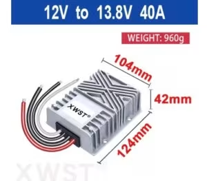
Check these basics before power is connected:
If the vehicle has complex electronics, stop-start technology, a smart alternator or a battery-management system, assess the electrical layout before proceeding. Some late-model vehicles need a more considered ignition trigger and charging arrangement. Guesswork is expensive when it affects the vehicle’s factory electrical system.
Remove the negative battery terminal first. Then mount the controller and relay in their selected locations. Keep the controller’s adjustment control or display accessible, but do not place it where it can be knocked by tools, cargo or routine servicing.
The relay should be close enough to keep high-current cable runs sensible, but it also needs protection from water and heat. In a four-wheel drive or work ute that sees creek crossings, corrugations or mud, use sealed components and route wiring higher where possible.
Run a suitably sized positive cable from the battery positive terminal to the fuse holder. The fuse belongs close to the battery – not at the other end of the vehicle. Its purpose is to protect the cable if it is damaged or shorted anywhere along the run.
From the fuse, supply the relay’s main power terminal. Use cable gauge and fuse capacity specified for your hydrogen kit. Do not substitute thinner wire because it is easier to route. Undersized cable causes voltage drop and heat, which reduces generator performance and creates a genuine failure risk.
The relay trigger needs a switched source so the HHO system cannot run with the key off. Select an ignition-switched feed that becomes live in the run position, not merely an accessory circuit that may power up when the engine is not operating.
Connect this trigger through the relay coil as shown in the kit wiring diagram, with the coil earth connected to a clean chassis earth point where required. Some installations use an oil-pressure switch or another engine-running signal for additional protection. That can be a smart option for commercial vehicles and generators, but it must be installed according to the system specification.
Avoid tapping into airbag, engine-management, safety or sensor circuits. A controller installation should support the engine, not interfere with the systems that keep the vehicle legal and safe.
The relay’s switched high-current output supplies the controller positive input. From the controller output, run the specified cable to the positive terminal of the hydrogen generator. Connect the generator negative terminal to a clean, secure earth point or directly to battery negative if the kit instructions call for it.
Prepare every earth point properly. Remove paint, corrosion and contamination until you have clean metal, fit the terminal tightly, then protect the finished connection against corrosion. A poor earth is one of the most common reasons a hydrogen system runs weakly, behaves inconsistently or shows misleading current readings.
Keep positive and negative cables neatly routed in conduit. Support them at regular intervals and leave enough slack for engine movement without allowing wires to rub against the firewall, radiator support or engine brackets.
Before reconnecting the battery, inspect every terminal and compare the circuit against the supplied diagram. Verify that the controller input receives switched positive power, that its output goes to the generator positive terminal, and that the generator negative has a sound earth. Reversed polarity can damage electrical components immediately.
Then reconnect the battery negative terminal. With the ignition off, the controller should be inactive. Turn the ignition to the required operating position or start the engine and confirm the relay switches on cleanly. Listen for the relay click, then check the controller indication and generator current draw.
Start at the recommended setting for your generator size. Let the engine reach normal operating temperature, then observe system current and the generator’s behaviour. A well-set system should operate steadily without excessive heating, aggressive bubbling or repeated fuse failures.
If the controller has an adjustable duty cycle, make small changes only. Give the system time to stabilise after each adjustment. Chasing maximum amperage may look impressive on a meter, but it can increase electrolyte consumption and heat without delivering a worthwhile engine benefit.
The right target depends on engine size, alternator capacity, kit configuration, electrolyte concentration and workload. A highway-driven diesel may behave differently from the same vehicle towing a trailer, just as a stationary generator behaves differently under changing electrical load. Record the setting, current draw and maintenance checks so you can identify changes early.
After installation, inspect the system again after the first drive or work cycle. Check that cables remain cool enough to touch after shutdown, terminals have not loosened and the fuse holder shows no heat damage. Inspect the controller mounting and cable ties after rough-road use.
Also monitor battery voltage and alternator performance. If the vehicle already has high electrical demand from driving lights, fridges, inverters, winches or auxiliary batteries, the charging system must have enough capacity for the hydrogen generator as well. For fleets, this check should be part of the installation standard across every vehicle, not left to individual drivers.
Hydrogen Fuel Systems kits are designed around practical engine applications, but installation quality still determines the result. A clean, fused, relay-controlled installation gives the controller the conditions it needs to do its job: manage current, protect the generator and support dependable operation. Take the extra time to wire it properly, then keep inspecting it as part of normal vehicle maintenance.
by Gavan Knox MSc, BSc, BEd, Inventor
WhatsApp call +61 403177183
contact gavan@hfuel.com.au
https://hydrogenfuelsystems.com.au
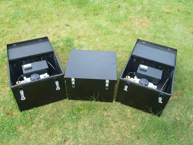
Brilliant Invention Gen 20 Hydrogen Generator ---(update Feb 7... Full Story
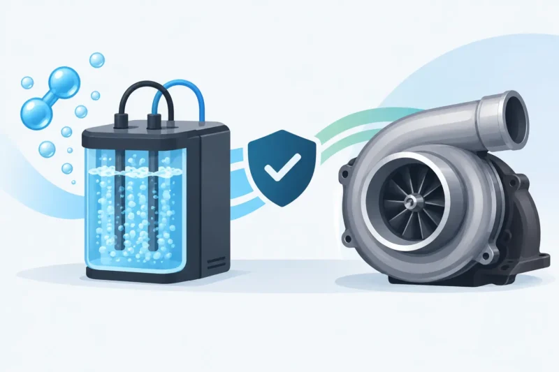
Will HHO Affect Turbochargers? Facts That Matter - Nov... Full Story
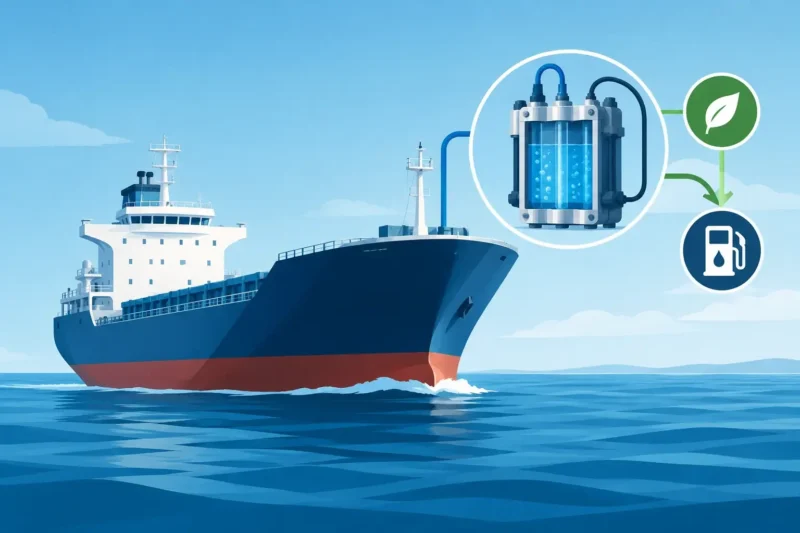
Marine Vessel HHO Fuel Trial for Real Fuel Savings... Full Story
HHO Kits That Make Hard-Working Engines Work - Nov... Full Story
Payment Methods Partner:

© 2026 Hydrogen Fuel Systems Pty Ltd