Brilliant Invention Gen 20 Hydrogen Generator July 2 2026
Brilliant Invention Gen 20 Hydrogen Generator ---(update Feb 7... Full Story
Perth, West Australia




by Gavan Knox MSc, BSc, BEd, Inventor
WhatsApp call +61 403177183
contact gavan@hfuel.com.au
https://hydrogenfuelsystems.com.au
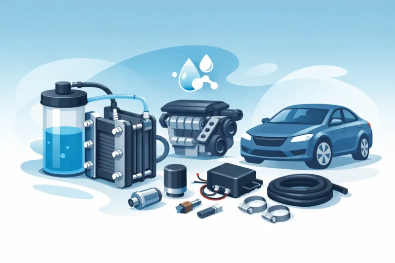
Complete Guide to HHO Kit Components for Better Results Aug 8. A hydrogen system is only as effective as the parts supporting it. A quality cell fitted with undersized wiring, poor hose routing or an unprotected electrical supply will not deliver the result you bought it for. This complete guide to HHO kit components explains what belongs in a properly engineered on-board hydrogen system and why every component matters to combustion efficiency, reliability and operating cost.
For a diesel work ute, long-haul truck, boat, generator or hard-working 4WD, the goal is practical: support a cleaner, more complete burn while protecting the vehicle and the kit itself. The right system is not a jar under the bonnet with a few wires attached. It is a matched assembly of gas-generation, water-management, electrical and installation components selected for the engine’s workload.
The generator cell is the centre of the system. It uses electrical energy and an electrolyte solution to produce hydrogen and oxygen gas on demand, which is then introduced into the engine’s intake system. Cell design determines gas output, current draw, heat management and long-term durability.
A properly built dry cell uses corrosion-resistant plates, controlled plate spacing, durable gaskets and a sealed housing. These details matter because the cell operates in a harsh environment of heat, vibration and electrical load. Poor plate material can deteriorate. Weak seals can leak. Inconsistent plate spacing can create uneven current flow and excess heat.
Generator size must suit the application. A small passenger vehicle does not have the same airflow, electrical capacity or duty cycle as a loaded diesel truck, marine engine or standby generator. Hydrogen Fuel Systems offers Gen 10, Gen 15, Gen 20 and Gen 25 configurations because one-size-fits-all equipment is rarely the best answer. Bigger is not automatically better. An oversized cell can create unnecessary electrical demand, while an undersized unit may not provide worthwhile support under sustained load.
The reservoir holds the water and electrolyte mixture that feeds the generator cell. It also provides a practical point for checking fluid level and topping up the system. This component needs to be mounted securely, kept away from direct exhaust heat and positioned where routine servicing is straightforward.
Water quality affects system cleanliness. Using suitable purified water helps reduce mineral deposits and contamination inside the cell, while the correct electrolyte concentration supports efficient operation. Too little electrolyte can limit output. Too much can drive excessive current, raise temperature and shorten component life.
This is one area where disciplined maintenance pays. Check the fluid level, inspect the colour and condition of the solution, and clean the system at the intervals recommended for the kit. A fleet vehicle covering serious kilometres needs a maintenance routine, not guesswork after a warning light appears.
Gas leaving the cell should not travel straight to the intake without protection. A bubbler, sometimes called a water trap or safety bubbler, acts as a barrier in the gas line. It helps prevent moisture and contaminants from reaching the intake, and it provides an additional safety measure against reverse flame travel.
The bubbler should be mounted upright, secure and accessible for inspection. Its fittings, lid and hose connections must remain airtight. A cracked bottle, loose cap or contaminated fluid can compromise the system.
Some installations also use an inline filter. This gives extra protection against electrolyte mist or debris moving downstream. On modern engines with sensitive intake sensors, turbo plumbing and intercooler systems, keeping the gas path clean is not optional. It protects the engine bay investment you already have.
HHO gas hose must be chemical-resistant, heat-tolerant and correctly sized for the system’s gas flow. Ordinary hose can harden, split or react with the electrolyte vapour over time. Every join needs a secure fitting and clamp, with routing that avoids sharp edges, moving belts, exhaust components and hot turbo housings.
The final intake connection is equally important. Gas needs to enter at a suitable point in the induction path so it is carried consistently with the incoming air. Placement varies by engine design. Naturally aspirated petrol engines, common-rail diesels, turbocharged 4WDs and marine engines all present different access points and airflow characteristics.
Do not drill, tap or connect into an intake tract without understanding what sits behind it. A poor connection can create an air leak, interfere with sensor readings or introduce material into the engine. Application-specific instructions and experienced installation are worth far more than a shortcut under the bonnet.
An HHO system depends on the vehicle’s electrical system, so the wiring must be treated as seriously as any auxiliary battery, winch or driving-light installation. The core electrical components normally include heavy-duty cable, a fuse, relay, connectors, earth leads and an ignition-switched trigger source.
The fuse protects the circuit if a fault occurs. It must be correctly rated and fitted close to the battery supply. The relay allows the cell to operate only when the engine is running or the ignition circuit is active, depending on the installation design. This prevents the system from draining the battery when the vehicle is parked.
Cable size matters. Undersized wiring creates voltage drop, heat and unreliable performance. Poor earth connections can cause the same trouble. Wiring should be protected in conduit where required, kept clear of abrasion points and secured properly rather than left hanging across the engine bay.
For heavy-duty applications, electrical load assessment is essential. A vehicle with refrigeration, lighting, communications equipment, dual batteries or other accessories may need a more detailed charging-system check. The alternator, battery condition and total accessory load all influence whether the system can operate as intended.
A controller manages current to the cell. Depending on the system, this may be a pulse-width modulation unit or another form of power regulation. Its job is to help maintain efficient electrical operation rather than allowing uncontrolled current draw.
This matters because cell performance changes with temperature, electrolyte condition and supply voltage. Without proper regulation, a generator can run hotter than necessary and consume more power than the application requires. Controlled power delivery supports more consistent output and helps protect the cell.
A controller should be mounted away from direct water splash and excessive heat, with adequate ventilation where specified. It is an electronic component, not something to cable-tie beside a hot exhaust manifold and forget about.
Some vehicles may require supporting components to work alongside modern engine management systems. Depending on the application, this can include sensor-related hardware or adjustments designed to maintain stable operating behaviour after the hydrogen system is installed.
This is where generic advice becomes risky. Modern diesel and petrol engines use complex feedback from airflow, temperature, boost, exhaust and fuel-control systems. The correct approach depends on the engine, its emissions equipment, the intended use and applicable Australian requirements. A modification that is suitable for an older mechanical diesel may be completely unsuitable for a late-model electronically controlled vehicle.
Never bypass or disable safety-critical or emissions-control equipment simply to chase a result. Any installation must be assessed for roadworthiness, warranty implications and relevant state or territory regulations. For commercial fleets, record the installation, monitor fuel use over comparable routes and let real operating data determine the value.
The best kit is the one matched to your engine’s operating reality. A suburban petrol car with short trips needs a different approach from a diesel LandCruiser towing a caravan, a rigid truck running interstate, or a generator operating at a steady load for hours at a time.
Before selecting a system, consider engine capacity, fuel type, alternator output, typical load, available mounting space and annual fuel spend. The higher the fuel consumption and the more consistent the duty cycle, the easier it is to measure any improvement accurately. A fleet operator should track litres per 100 kilometres, idle time, payload, route conditions and service intervals. A generator owner should track fuel consumed per operating hour at a consistent load.
The quality of the installation is part of the product. Secure mounting, protected wiring, tidy hose routing and a serviceable reservoir make the difference between a system that is easy to maintain and one that becomes an engine-bay headache.
After the first runs, inspect the cell, reservoir, wiring and hoses regularly. Look for loose fittings, fluid seepage, discoloured wiring, unusual heat, hose wear and changes in fluid level. Check that the fuse, relay and controller are operating correctly and that no warning lights or drivability concerns have appeared.
Fuel-saving and performance outcomes vary with engine condition, driving style, load, tuning, maintenance history and duty cycle. A healthy, well-serviced engine gives any combustion-enhancement system a better platform to work from. If injectors, air filters, turbo hoses or sensors are already causing problems, fix those first.
Build the system properly, install it to suit the vehicle, and measure it against genuine operating figures. That is how an HHO kit moves from an aftermarket accessory to a serious tool for reducing fuel costs and getting more useful work from every tank.
by Gavan Knox MSc, BSc, BEd.
WhatsApp call +61 403177183
contact gavan@hfuel.com.au
https://hydrogenfuelsystems.com.au
Brilliant Invention Gen 20 Hydrogen Generator ---(update Feb 7... Full Story

by Gavan Knox HFS whats app +61 403177183 gavan@hfuel.com.au... Full Story

Fuel Economy Methodology That Produces Real Numbers - oct... Full Story

Can HHO Improve Towing Economy? Facts That Matter -... Full Story
HHO Versus Additives: What Actually Pays Back? - Oct.... Full Story
Payment Methods Partner:

© 2023 - Hydrogenfuelsystems pty ltd